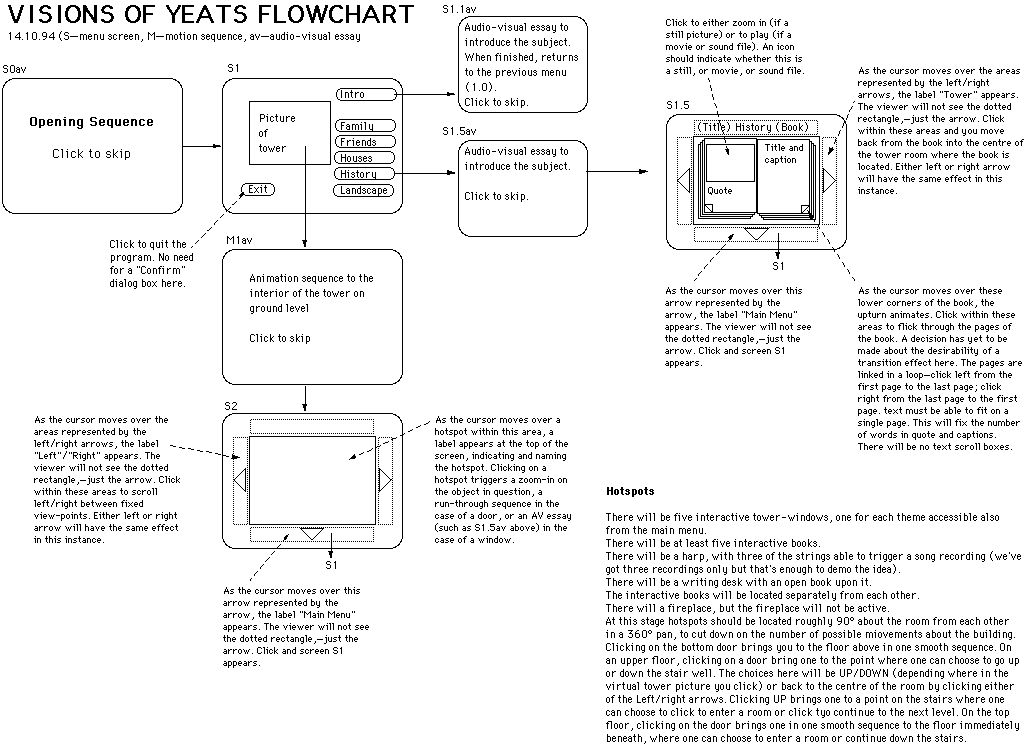
Flowcharts are schematic representations of the interactive flow of a program, usually produced by the interactive designer. (Link to an example of a program flowchart -- 48k filesize.) All possible user interaction pathways, expressed through labelled boxes and directional arrows, are traced through any hierarchical menu tree structures and along various screen branches.
Detailed interactive-program flowcharts can be extremely complicated and extremely large, occupying whole office walls. Roles of blank wallpaper can be used to accommodate diagrams of this scale. In one example, a client-writer produced a hand-coloured, wallpaper chart of over ten metres in length to express their initial concept. Beautifully executed, it contributed greatly to the success of the final program design and had the additional benefit of involving the client very intimately in the design process. Such 'monumental' approaches to visualising the program can be avoided, however, by means of a flowchart which is carefully cross-referenced to a detailed storyboard.
The technique of interactive storyboarding (discussed within the 'storyboard' link above) is an alternative means of communicating the design content and flow structure of a program. It is an approach which is meant to complement printed flowcharts and storyboards rather than replace them.
Claris CAD on the Mac was used to produce the flowchart used to illustrate this section. Any draw package would be suitable.